The I/O pins used for some PIC32MK peripherals are set by the user application code. The pin assignments for these peripherals are not predetermined by Microchip. The process of assigning I/O pins to peripherals on the PIC32 is called Peripheral Pin Select (PPS).
When an application does not use all the peripherals on a device, PPS allows you to select a smaller pin-count package thus saving board space and potentially reducing cost. The ability of PPS to place peripheral functions on select pins can also be useful in optimizing board layout.
Requirements for PPS
Digital Peripherals
Most digital peripherals use PPS. Analog peripherals and digital peripherals with special I/O characteristics (e.g. I2C) do not accept PPS assignments. The pinouts for these peripherals is fixed and cannot be reprogrammed. The PIC32MK PPS peripherals are:
- External Interrupts
- Quadrature Encoders (QEI)
- Timer/capture/compare
- CAN
- UART
- SPI
Package Pins
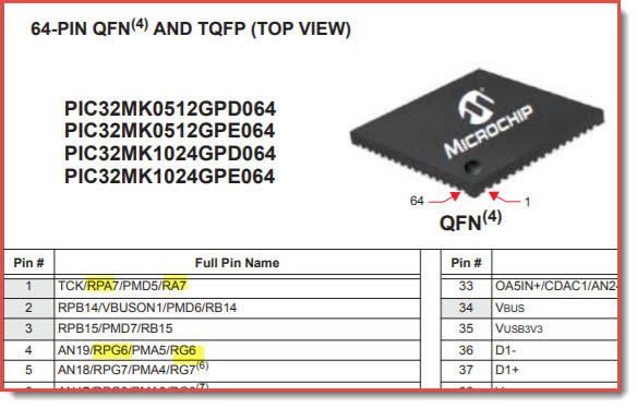
Re-programmable pins are designated on the datasheet with the prefix 'RP' such as RPA1. By design, re-programmable pins are also designated as digital I/O pins assigned to a PORT with a similar name. For example, RPA7 can be used a digital I/O RA7, RPG6 as RG6 and etc.
Programming PPS
There is a special function register (SFR) for each PPS capable peripheral function. There is also an SFR for each re-programmable pin.
- To assign a pin as an input to a peripheral function, write the numerical code for the desired PPS pin into the peripheral function's SFR
- To assign the output of a peripheral to an RP pin, write the code associated with the peripheral function into the RP pin's SFR.
Before a PPS pin can be used, ANSELx and TRISx must be programmed to ensure that the pin is digital and the data direction matches the PPS assignment.
Register name, peripheral/pin codes
The name of a peripheral function SFR is the name of the peripheral function followed by the letter 'R'. For example, INT uses INTR and Timer 5's input clock (T5CLK) uses T5CLKR. "TABLE 13-1" in the PIC32MK data sheet contains the full list of register names.
The codes written to the peripheral function register designating which pin is to be assigned are listed in
"TABLE 13-1" of the datasheet.
Use care when studying "TABLE13-1" as there are some overlapping of code usage. The number five (0101b) when written to T3CKR designates RPA8 as the input. When five is written to INT4R, RPC7 is designated as the input.
Read the Data Sheet for the part you are using!
The names of registers associated with PPS begin the with the pin's RP name and end with the letter 'R' (RPA3's SFR is RPA3R, RPG3's is RPG3R, etc..). The full list of registers can be found in "TABLE 13-2" of the PIC32MK data sheet.
"TABLE 13-2" also contains the codes associated with the peripheral functions assigned as outputs. As with the input values care should be taken when using "TABLE 13-2". The codes for the peripheral functions change depending upon which pin they are being assigned.
Programming Examples
Setting a UART's TX pin.
The following code establishes an analog capable RP pin (RPB9) as TX2OUT. Please note the value 2 on line 5 was read from "TABLE 13-2" of the PIC32MK datasheet.
Setting QEI Inputs.
The following code initializes the inputs for QEI module 2. Analog capable RPE14 is set as QEB2, digital-only RPC9 is set as QEA2. The value written on lines 2 and 6 (5 and 8 respectively) were obtained from "TABLE 13-1".