Objective
This article describes the process of creating a simple weather and Bluetooth® application using a PIC16F1719, a MikroElektronika Weather click™ board, and a BLE2 click™ board to send environmental data over Bluetooth to a mobile phone application.
Materials
Hardware Tools
Software Tools
| Tool | About | Installers |
Installation
Instructions |
||
|---|---|---|---|---|---|
| Windows | Linux | Mac OSX | |||
|
MPLAB® X
Integrated Development Environment |
| | | | |
|
MPLAB® XC8
C Compiler |
| | | | |
 MPLAB® Code Configurator
Dynamic Code Generation |
| | |||
HARDWARE SETUP
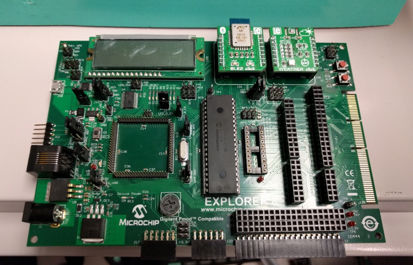
Make sure the following jumpers are present on the Explorer 8 Development Board to ensure that the project functions properly:
- No need for any jumpers on components one through three in the following image.
- In component four, configure the jumpers such that:
- J53, J55: RC7 is connected with the center pin to configure it as the microcontroller RX pin that connects the microcontroller UART RX pin to the MCP2221 TX pin.
- J54, J56: RC6 is connected with the center pin to configure it as the microcontroller TX pin that connects the microcontroller UART TX pin to the MCP2221 RX pin.
- No need for any jumpers on components five through seven in the following image.
- In component eight, configure the jumpers such that:
- J27, J43: RC7 is connected with the center pin to configure it as the microcontroller RX pin that connects the microcontroller UART RX pin to the J32 mikroBUS UART RX pin.
- J34, J44: RC6 is connected with the center pin to configure it as the microcontroller TX pin that connects the microcontroller UART TX pin to J32 mikroBUS UART TX pin.
- No need for any jumpers on components nine through eleven in the following image.
- In component 12, configure the jumpers such that:
- J37: RA6 is connected with the center pin to configure the 8 MHz crystal to connect to the MCU OSC2/RA5 pin.
- In component 13, configure the jumpers such that:
- J36: RA7 is connected with the center pin to configure the 8 MHz crystal to connect to the MCU OSC1/RA7 pin.
- No need for any jumpers on component 14 in the following image.
- In component 15, configure the jumpers such that:
- J14, J30: The board is supplied with 3.3 V.
- In component 16, configure the jumpers such that:
- J2: The board is supplied with 5 V power via the output of the 5 V regulator.
- In component 17, configure the jumpers such that:
- J51, J52: RB7 is connected with the center pin at J51, and RB6 is connected with the center pin at J52 to connect the PGD and PGC pins of the ICD to the PIC® MCU ICSPDAT and ICSPCLK respectively for In-Circuit Serial Programming (ICSP™).
- No need for any jumpers on component 18 in the following image.
- In component 19, configure the jumpers such that:
- J24: The two pins are connected to each other to supply a regulated 3.3 V output to the mikroBUS.

Procedure
The major steps to implement in this project are as follows:
- Setup Project Resources
- Setup click boards
- Setup Pin Manager
- Generate Code
- Add Functionality
- Program the Device
Setup Project Resources
1
Create New Project
Create a new stand-alone project in MPLAB X IDE for a PIC16F1719. If this is your first time using MPLAB X IDE, follow the instructions in the following article: "Create a Standalone Project".
2
Launch MPLAB Code Configurator (MCC)
Open MCC under the Tools > Embedded menu of MPLAB X IDE as shown in the following image.

3
Set Up System Module
The System Module needs to be set up. Under the Project Resources window, click on System Module.
The System section will appear. In this section, the oscillator settings and the configuration settings are selected.
Oscillator
- Select the HS Oscillator, High-speed crystal/resonator connected between the OSC1 and OSC2 pins from the drop-down menu for the Oscillator Select option.
- Select FOSC from the System Clock Select drop-down menu.
- Select the External Clock as 8 MHz
- Check the Low-voltage programming Enable selection.
The System Module will look as follows when you are finished:

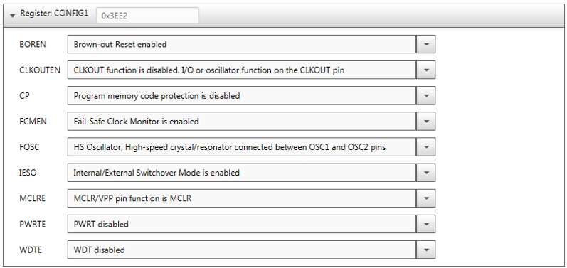
Configuration
Each configuration setting can be changed under the Register tab of the System window.
Verify that the MCC generated settings are set to the default values shown here:

Setup Click Boards
4
Set Up Weather click
At this point, it may be useful to watch the YouTube video on loading the MikroElektronika click Libraries. The libraries are found in the Device Resources window. Scroll to the bottom of the window to see the Mikro-E Clicks drop-down menu.

In the drop-down menu, double-click on Mikro-E Clicks > Sensors. You will see a sensor label named "Weather". Double-click on Weather to successfully open the Weather click window to the right, which consists of the Weather click board’s information, configuration, and advanced settings.


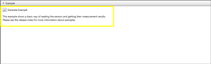
Click on the Configuration tab to reveal a brief description of what the generated code example is supposed to do.
5
Configure Pin Manager (Weather click)
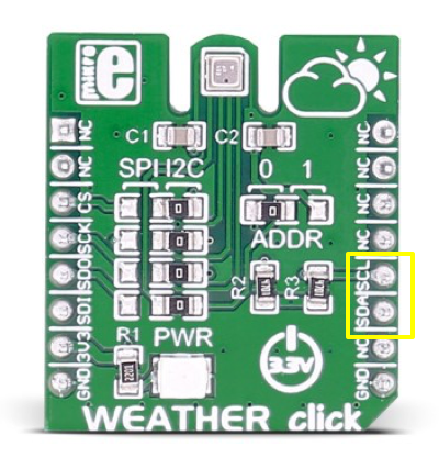
Once you have finished loading the Weather click, the next step is to set the correct pins in the Pin Manager. The Weather click communicates directly with the PIC16F1719 over the Serial Peripheral Interface (SPI)/I²C. In this project, we are using I²C. The resistors are soldered according to the picture below.
When choosing the Weather module in MCC, the Foundation Services Library automatically generates a predefined I²C Master Synchronous Serial Port (MSSP) module as well. If you click on the MSSP label in the Project Resources menu, you can see that Enable I2C is checked. It should look like the following window:

The only pins you need to set for the Weather click are SDA and SCL. When you look at the physical Weather click and Explorer-8 Development board pin connection, you will see that SCK/SCL is connected to pin RC3, and SDA is connected to RC4. Update the pins and check to make sure your window looks like the one below.

6
Set Up BLE2 Click
On your computer, return to the MCC window and click on Device Resources. Scroll down and double-click on the Mikro-E Clicks > Wireless Connectivity > BLE2. If done correctly, the center window in MCC opens the BLE2 click board’s information, configuration, and advanced settings.


Clicking the Configuration tab reveals a brief description of what the generated code example is supposed to do.

The description tells us the example configures a custom profile called “MLDP” on the BLE microcontroller, which allows you to send strings or binary data via Bluetooth communication. To read more about the MLDP and other modes of the RN4020, visit the RN4020 Operating Modes page.
7
Configure Pin Manager (BLE2 click)

Find the first pin (Cmd_Mldp) in the Pin Configurator and see which pin it connects to on the Explorer-8 Development Board. This project uses the J32 socket on the Explorer 8 board for BLE2 click; this pin connects to pin RC0. The Conn pin connects to pin RE0 on the Explorer 8 Development Board and the Wake pin connects to RD7.

The BLE2 click communicates directly with the PIC16F1719 over UART serial communication. When you add the BLE2 module in MCC, the foundation services library automatically generates a predefined EUSART module as well. The BLE2 click board's baud rate is fixed at 115200; you can change it using the commands available in the datasheet.

It is necessary to define the pins the microcontroller uses to communicate with the BLE2 click. The PIC16F1719 TX line needs to connect to the RX line on the BLE2 click (pin RC6). Similarly, the RX line on the PIC16F1719 should be connected to the TX line on the BLE device using the pin RC7. Once you have completed all the pin selections, it should look like the window below.

8
Additional Pin Configuration
Pin Module/GPIO/input: Port RB0 – For enabling interrupts via the pushbutton connected to pin S1.
Reset: Port RE3

9
Custom Name for Pins
Close the Pin Manager and then click on the Pin Module in Project Resources section.

Rename the GPIO pins to something more user-friendly to use in our code. In the main MCC viewer window, find the RB pin and change the Custom Name field from IO_RB4 to S1 as shown below.

10
Generate Code
Click on Generate Code to have MCC create the software libraries for this project.

The project will now have generated header files, source files, and a main.c file.

11
Coding the Application
After generating code, the Output window of MCC should have successfully created your code and prompted you to save the MCC Configuration file.
Under the Projects window in the MPLAB X IDE, you will find the MCC generated files along with the main.c file for your project. Among the files are a set of example projects that Microchip included as part of its "50 Clicks in 50 Days campaign, two of which you will be using for this project.
Click on Header Files > MCC Generated Files > Example_BLE2.h to open the example code generated for the BLE2 click. Every click that is supported in MCC generates an example header file like this to provide a jumping off point for further projects. You will be using the first two functions, void EXAMPLE_setupBLE2 (const char* name); and void EXAMPLE_sendMessageOverBLE2(uint8_t *message); for this project.

Navigate to your project’s main.c file in the Projects window under Project Name > Source Files and double-click the file to open it. In the main viewer window, you will see that the program is empty, which you are about to change.

In main.c, include the mcc_generated_files/EXAMPLE_BLE2.h file. Within the main function, call the function EXAMPLE_setupBLE2(); with a string parameter. This function uses a character string to set the name of your BLE device.
It is necessary to enable interrupts for the BLE2 example code to work properly. Below SYSTEM_Initialize(), uncomment the lines that say INTERRUPT_GlobalInterruptEnable() and INTERRUPT_PeripheralInterruptEnable(). After making these changes, main() should look as shown below:
There are two files, weather.c and weather.h, in which you need to include additional functionalities. Open the weather.h file and declare the following functions:
Also, make sure to include the math.h header file (#include <math.h>) in the file as well.
The weather application shows how to read humidity in %RH, the pressure in KPa, and the current temperature in degrees Celsius (°C) from the BME280 over I²C.
The function Weather_getTemperatureDegF() computes the temperature in degrees Fahrenheit (°F) using the current room temperature in °C as shown in the following code snippet:
The Weather_HeatIndexDegC() function computes the Heat Index in °C using the current room temperature in °C and humidity.
The index is approximated using the following formula:
(1)Where, HI = heat index, T = Temperature (°C/°F), R = Relative Humidity, and c1 - c9 are the default set of constraints for this equation. Equations were found on Wikipedia.
The Heat Index is an index that combines air temperature and relative humidity in shaded areas, as an attempt to determine the human-perceived temperature. It is also known as "felt air temperature".
The following code snippet shows how to compute the heat index in °C:
This project also provides a code snippet to compute the heat index in Fahrenheit as shown below:
The function DewPointDegC() computes the Dew Point in °C using the current room temperature in °C and humidity.
The index is approximated using the following formula:
(2)Where TD = Dew Point, T = Temperature (°C), and RH = Relative Humidity. These equations were provided by Brian McNoldy.
The dew point is the temperature to which air must be cooled to become saturated with water vapor. When further cooled, the airborne water vapor will condense to form liquid water.
The function DewPointDegF() computes the Dew Point in °F using the current dew point in °C, as shown in the code snippet below:
Now open the weather_example.c file under Source Files in the Projects window. The source file shows the specific operations the Weather_example() function accomplishes. Notice how the function reads the temperature, pressure, and humidity data and then prints each of these values. Instead of printing them to the UART for serial communication purposes, you will create a string and send the data using the example BLE function.
Add five arrays with 50 characters each under the include statements in the weather_example.c. Also, make sure to include the BLE example file as well:
Then, change:
to:
Now the data strings are each held in an array that we can call using the BLE Example function.
In order to get the two click boards to work together, we are going to use the BLE2 generated function EXAMPLE_sendMessageOverBLE2() to send the Weather click data over Bluetooth.
Add the following underneath the sprintf statements:
Return to the main.c file and in order to avoid spamming the smartphone application with constant data, you now need to bring the GPIO pin on port RB0 (that we earlier labeled "S1") back into the equation. Within the while (1) loop add the following:
This statement indicates that when the S1 push button is pressed, the subsequent code should be executed. If it isn’t, it should not do anything. Within the if condition call the weather example function by adding the line Weather_example(). Under the other #include lines at the top, include the weather example header file by adding #include "mcc_generated_files/weather_example.h".
Your main.c file should now look as follows:
12
Programming the Device
Make sure your project has the programming tool selected and has power connected to your development board. Click on the Make and Program Device icon. This will build the project and launch the programmer. In the Output window you should see a series of messages and if successful, it will end with a "Programming/Verify Complete" message.

Open the Android™ phone application by Microchip Technology named “MLDP Terminal” which is set to communicate with the Microchip Low-energy Data Profile (MLDP) communication protocol specifically. The application apk file can be found in the Software Tools section of this project.
The Android phone application appears similar to the image below:

Once you open the application, it should scan for nearby BLE devices and recognize “Weather” or the name you entered in the EXAMPLE_setupBLE2 (“Weather”) field. Select Connect in the app and once the application is connected, a green CONN LED will illuminate on the BLE2 click hardware.

Once the device is connected and the application is opened, you can see the terminal screen with DISCONNECT on the top right corner. It means that the device is connected and ready to stream data.

Now, press the S1 pushbutton on your Explorer-8 Development board and the phone application will display the humidity, temperature, pressure, Heat Index and Dew Point values as shown here:

If you want to use an iOS® phone application you can download “Bluetooth Smart Data” by Microchip Technology, which is set up to communicate with the Multicast Label Distribution Protocol (MLDP).

13
Closing the Project
The project can be closed in MPLAB X IDE. It is automatically saved when it is built, but if any changes to the files or configuration were made, MPLAB X IDE will ask you to save them before the project is closed. The project can be closed under File > Close Project.

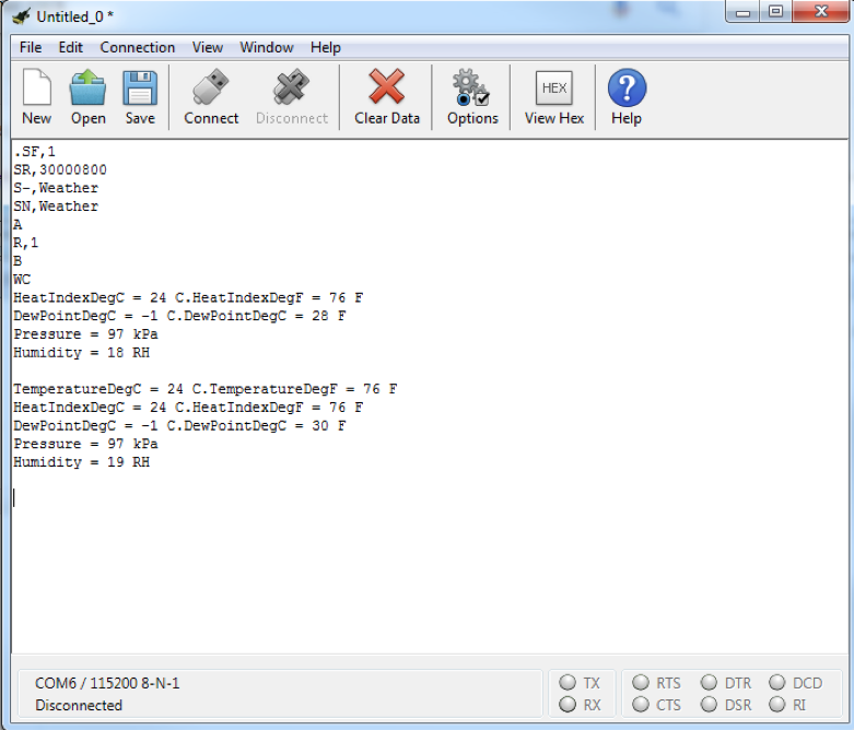
Troubleshooting
If you want to troubleshoot or verify what data is streaming through Bluetooth, you can use a terminal program. We have used a CoolTerm for Windows® serial communication terminal to print the data being streamed.
Download the Source Code.