Summary
Graphics Objects are predefined entities provided by the MLA which are drawn on the display under the control of an embedded application. Graphics objects make data seen by the application program visible to the user. If the system has a touch screen capability, Graphics objects can also be used to input user commands.
Although previously designed Graphics Object can be easily modified to suit the visual requirements of an application.
This section of the tutorial covers:
- Creating Graphics Objects
- Drawing Graphics Objects on the screen
- Controlling the appearance of Graphics Objects
Updating the values displayed by the Object and getting user input from the objects are covered in the next two sections of this tutorial.
Examples of Graphics Objects
This page contains information for the Graphics Library found in the Microchip Libraries for Applications (MLA). It is not relevant for the MPLAB® Harmony Graphics Library.
In order to use graphics objects in a project, the files gfx_gol.c and gfx_gol.h must be included in the project.
The GFX_Initialize() function must also be executed before any other object related functions are called.
The list of available graphics objects include:


 help_mla_gfx.jar located in …microchip/mla/vYYYY-MM-DD/doc….
Creating Graphics Objects
This page contains information for the Graphics Library found in the Microchip Libraries for Applications (MLA). It is not relevant for the MPLAB® Harmony Graphics Library.
Graphics objects are created at run-time. Before a screen is initially drawn, the application calls a sequence of object-creating functions. Each of these functions creates a data structure for an instance of an object. Parameters passed to the object-creating functions determine the location, size, state, and colors of the object. In addition to the commonly shared parameters just mentioned, many object functions accept parameters unique to the specific objects.
The created data structures are placed in a single linked list. The drawing function (GFX_GOL_ObjectListDraw) reads the objects state bits in the display list, then updates the frame buffer as needed.
All object creating functions return a pointer to the memory location of the data structure they create. The object structures are kept in the heap memory of the PIC® MCU's RAM.
Before graphics objects can be used, you must modify the MPLAB X IDE's project to set up the heap. To determine the specific heap size needed by a graphics application, see the "Heap Requirements for Graphics Objects" page.
Object Creating Functions
Below is a partial list of the functions used to create objects:
| Object | Create Function |
Object Unique Input Parameters |
|---|---|---|
| Button | GFX_GOL_ButtonCreate() | radius - the roundness of the buttons |
| Digital Meter | GFX_GOL_DigitalMeterCreate() | value - initial value NoOfDigits - number of digits DotPos - location of decimal point |
| Scroll Bar | GFX_GOL_ScrollBarCreate() | range - highest possible value page - incremental value change pos - initial slider position |
| Group Box | GFX_GOL_GroupboxCreate() | alignment - text alignment designation for the group box |
| Check Box | GFX_GOL_CheckBoxCreate() | n/a |
help_mlagfx.jar located in ..microchip/mla/vYYYY_MM_DD/doc….Example: Creating a Screen With Two Buttons and a Slider

When preparing to use graphic objects in a project, two steps need to be taken:
- Ensure GFX_GOL.h and GFX_GOL.c are added to the project.
- Add the source and header file for the particular object in the file. For example: since the steps below show at least one button and one slider, GFX_GOL__Button.c/GFX_GOL_Button.h and GFX_GOL_ScrollBar.c/GFX_GOL_ScrollBar.h need to be added to the project.
When drawn to the screen, the structure created by the function, Create_Screen (below), will display:
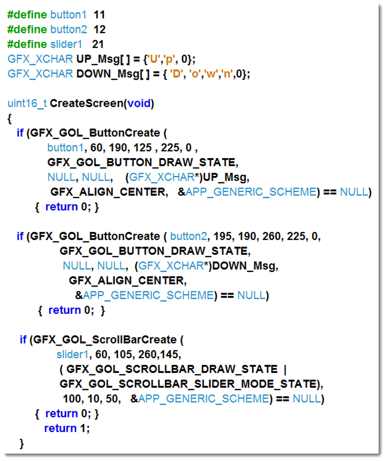
In the example above, Create_Screen calls several instances of object-creating functions. When an object is created, the creating function returns a pointer to the location in memory where the object has been placed. If for some reason the object is not successfully made, then a NULL is returned. In this example, the function Create_Screen is written to return a "true" if all the objects were successfully created. If any object was not able to be created, then Create_Screen will return a "false."
Style Scheme
This page contains information for the Graphics Library found in Microchip Libraries for Applications (MLA). It is not relevant for the MPLAB® Harmony Graphics Library.
- Style Scheme
- A style scheme is a data structure that determines how an object will be rendered on the screen. Style schemes contain all the colors, images, fonts, and text used in displaying an object. Style schemes are defined independently of objects. Upon the object’s creation, a user-defined style scheme is assigned to the object. A single style scheme may be assigned to many different objects.
Structure of a Style Scheme
The structure GFX_GOL_OBJ_SCHEME is used to hold instances of style schemes. GFX_GOL_OBJ_SCHEME is defined in GFX_GOL_SCHEME.h.
Styles schemes contain at least 16 items. Additional items will be added if Alpha Blending defined in GFX_CONFIG.h or Gradient Color Filling defined in GFX_CONFIG.h are enabled.
When an object is displayed, elements from the style scheme are applied to object based upon the state bits of the object.
| Structure Member |
Function |
| EmbossDkColor | Dark color used for the 3-D effect of the object. |
| EmbossLtColor | Light color used for the 3-D effect of the object. |
| TextColor0 | Generic text colors used by the objects. Usage may vary from one object type to another |
| TextColor1 | Generic text colors used by the objects. Usage may vary from one object type to another |
| TextColorDisabled | Text color used when the object state bit is set to "disabled" |
| Color0 | Generic color used to render objects. Usage may vary from one object type to another |
| Color1 | Generic color used to render objects. Usage may vary from one object type to another |
| ColorDisabled | Color used to render objects that are disabled |
| pFont | Pointer to the font table used by the object |
| fillStyle | Determines gradient type. Only used when Color Gradients are enabled |
| ComonBkColor | Used to hide objects from view without deleting them. |
| ComonBkLeft | Horizontal starting point of the background |
| ComonBkTop | Vertical starting point of the background |
| ComonBkType | Specifies the type of background to use. |
| *ComonBkImage | pointer to an image used as the background image |
| EmbossSize | Size of the pannel for 3-D effects. Will be set to 0 if 3D is not used. |
| AlphaValue | Alpha value used for alpha blending, this is only available only when GFX_CONFIG_ALPHABLEND_DISABLE is not commented out in gfx_config.h |
| gradientStartColor | Starting color for gradient color scheme. Only exists when GFX_CONFIG_GRADIENT_DISABLE is not commented out in gfx_config.h |
| gradientEndColor | Ending color for gradient color scheme. Only exists when GFX_CONFIG_GRADIENT_DISABLE is not commented out in gfx_config.h |
Default Style Scheme
If the file gfx_gol_scheme_default.c is added to a project, it will create a style scheme called GOLSchemeDefault. The default scheme will be populated with the colors defined in gfx_gol_scheme_default.c. This default scheme maybe used as is, or may be modified to meet the application needs.
Creating and Using Style Schemes
It is quite common for an application to use several different style schemes. To create a style scheme, several steps must be taken:
- Create an instance of the style scheme structure and give it a name.
- Populate the newly created structure with the desired style scheme elements.
- Assign the new style scheme as graphic objects are created.
For instances where only a few elements of a new style scheme differ from an existing style scheme, many programmers find it more convenient to copy an existing scheme into a newly defined scheme, then edit the few different elements.
Example: Creating and Using a Custom Style Scheme
The following steps presume the gfx_gol_scheme_default file has been added to the project, resulting in the creation of a default scheme GOLSchemeDefault.

Create a pointer to a style scheme structure. In this example, the pointer is called MyNewScheme.

Copy the content of the exisitng default scheme to the newly create scheme.

Modify the contents of the scheme as needed to meet the application requirements. For this example, several of the elements of the new scheme have been modified.

Asssign the newly created style scheme to an object.
This page contains information for the Graphics Library found in Microchip Libraries for Applications (MLA). It is not relevant for the MPLAB® Harmony Graphics Library.
State Bits
Every graphics object has several state bits. The state bits are combined together into one word and stored in the object's data structure. State bits fall into one of two different categories:
The first category informs the drawing function, GFX_GOL_ObjectListDraw, to copy the entire object, or a portion of the object, to the frame buffer.
The second category of status bits informs GFX_GOL_ObjectListDraw how to draw the object. When an object is being copied to the frame-buffer some of the state bits inform GFX_GOL_ObjectListDraw which elements from the style scheme are to be applied to the object.
Examples of the GFX_GOL_ObjectListDraw applying a style scheme to an object based on the state bits are covered in the "Drawing Graphics Objects" Developer Help page.
State Bits used to Draw or Re-draw an Object
GOL_OBJ_xxxx_DRAW_STATE and GOL_OBJ_xxxx_DRAW_UPDATE_STATE are the state bits used to determine if an object is to be drawn or redrawn to the frame buffer.
The "xxxx" in the state bit names above are representative of the type of object to be drawn. There are no state bits with an xxxx in their name.
All objects have a DRAW state bit. When this bit is set, the entire object is written (or re-written) to the frame buffer. Typically, the user program sets the DRAW bit when a situation occurs in which the entire object needs to be redrawn.
Some objects have an UPDATE status bit in addition to the DRAW bit. When the update bit is set by the user application, only the portion of the object which contains data (such as the value on the meter object) will be re-drawn to the frame buffer. Using the UPDATE bit will help reduce the visual "jitter" that some people notice when an entire object is redrawn.| Object | DRAW State bit | UPDATE State bit |
|---|---|---|
| Button | GFX_GOL_BUTTON_DRAW_STATE | n/a |
| Meter | GFX_GOL_METER_DRAW_STATE | GFX_GOL_METER_UPDATE_DRAW |
| Scroll Bar | GFX_GOL_SCROLLBAR_DRAW_STATE | GFX_GOL_SCROLLBAR_THUMB_DRAW_STATE |
| Static Text Box | GFX_GOL_STATICTEXT_DRAW_STATE | n/a |
| Progress Bar | GFX_GOL_PROGRESSBAR_DRAW_STATE | GFX_GOL_PROGRESSBAR_DRAW_BAR_STATE |
elp_mlagfx.jar located in …microchip/mla/vYYYY_MM_DD/doc…State Bits Used to Control an Object's Appearance
In addition to the draw and update state bits, Graphics objects each have the following bits:
- GFX_GOL_xxxx_DISABLED: Draws the object with ColorDisabled and TextColorDisabled
- GOLgfx_xxxx_HIDE: Draws the object with the CommonBkColor from the style scheme, making the object non-visible
- GFX_GOL_xxxx_FOCUS: Applies a focus element to the object
The "xxxx" in the update-state bit names above are representative of the type of object to be drawn. There are no state bits with an xxxx in their names. Examples include names such as: GFX_GOL_BUTTON_DISABLE, GFX_GOL_METER_HIDE, etc…
In addition to the draw and update state bits, each object type has some states unique to that object. These unique state bits reflect conditions applicable to those objects. Comparison of the state bits for a Button object and a Scroll-bar object reveals some of the differences:
| Button States | Scroll-bar States |
 |
 |
| Object Specific States in yellow: |  |
The function and effect of setting the object-specific state bits vary from object to object. This tutorial will show you the procedures used to set and clear state bits. Refer to the help file to learn about the attributes of object-specific state bits.
Examples of programming changes to the state bits of the object are covered in the "Changing the State of Graphics Objects" Developer Help page.