A number of different techniques can be used to implement a Proportional, Integral and Derivative (PID) in a dsPIC®. Microchip offers a number of tools that can be efficiently used in implementing the algorithm, including the MPLAB® XC16 compiler and the Digital Signal Processor (DSP) library. The approach that has been used in the current module is to introduce some advanced techniques to take the maximum possible advantage of the dsPIC itself. The reason for this is the that in the production of a product, the designer has almost always finding ways to optimize the performance of the system, usually in terms of response time and transient response behavior.
You will become familiar with the relevant internal registers and will learn how to design with fast and efficient PID code. You will also learn how to squeeze the maximum accuracy from the system. The importance of getting the maximum accuracy will lead to maximum system performance.
The following figures present how a fast-, high-performance PID is implemented using the specific dsPIC hardware (DSP engine).
The architectural blocks used are:
- RAM, for storing coefficients and input error values
- Two 16-bit registers (W4 and W5) used to store data
- Two 16-bit registers (W8 andW10) to store pointers to RAM locations
- One 40-bit accumulator

The Coefficients area in RAM stores the Ka, Kb, Kc coefficients of the system. These values are fixed and will not be changed during the system operation.

The Errors area in RAM stores the error values. What is shown is the buffer status before a new PID output is computed (it will be understood later).
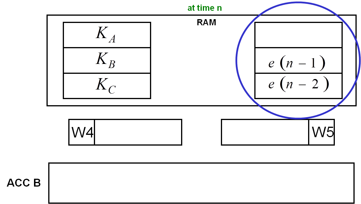
e(n-1) and e(n-2) are equal to zero at n=0; then they are updated at each step.
At time n, the accumulator contains the previous value of the PWM active period.

Below is the high level block diagram of the PID implementation
